 CLOSE SIDEBAR
AR 01 - Swing Chute – Part Separator for Injection Moulding Machine
Automation & Robotics Projects
As part of the course “366- Design and Development-2” of the Robotics and Automation Technology program, this project contributes to meeting the requirements to reduce manufacturing cost, manual part handling, and work cell footprint for one of the injection molding machines at KB Components Toronto. The company dedicated to the manufacture of plastic-injected parts for the automotive industry is always looking for different automated solutions for collecting parts from its injection machines. The conceptual design presented in the project is the result of research into different options for part-separators available on the market for similar applications. Based on the data collected and taking advantage of the experience of the company’s staff and the process and machine conditions, the solution of a Swing Chute was proposed.
Project objective
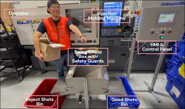
The objective of the project consists of the mechanical and electrical design, construction, assembly, and programming of a swing chute to automatically divert 6 different types of parts coming out of a Shibaura EC85SXII injection molding machine and direct them to good or reject bins located at each side of the chute. To accomplish this, the chute communicates with the molding machine to know when it is time to move to the position that will send parts to the reject or good side after each shot. The swing chute is required to run in a continuous cycle with the molding machine in production, with a visual means of interaction (HMI) and electrical safety circuit and a safe operation.
Mechanical design
The swing chute design is mainly a box that has a flapper that swings completely from one side to the other allowing parts to go to one side. The flapper is mounted on a shaft and moved by a lever mechanism with a pneumatic cylinder. The main box is mounted on a frame whose height can be adjusted. A couple of chutes on each side guide the parts whether good or rejected parts. The pneumatic elements used in air conditioning (pressure regulator and pneumatic valve) are attached to the frame as the chute is a stand-alone unit. An eight-part hopper collects the parts falling from the mold and directs them toward the main box of the chute. The hopper is a separate part from the chute and it is mounted to the frame of the machine by attaching a bracket to the frame and a hanger that holds the hopper in position under the machine tie-bars and the mold. All components except for the aluminum frame are fabricated in stainless steel as required by the company. For the control side, an electrical panel and its own frame are placed beside the machine and connected by a cable.
Design for safety
The swing chute design was proven to operate safely. Since the chute has moving parts, the use of guards helps isolate the end user from them. Following the guidelines for opening allowance for safe operation given by the Department of Industrial Relations in the 1910 - Occupational Safety and Health Standard, the machine has:
• Two main box guards that close the main box and block any access from the side to the swinging mechanism.
• Two chute guards that close the side chutes from above, therefore people can only grab parts from the bins and not from the chute.
Easy installation
The chute has an adjustable height so it can easily fit inside the machine frame beneath the mold while the hopper hangs from the brackets mounted on either side of the frame just below the tie bars. Both parts remain in the machine even during mold change. This design of the chute can be adapted to other injection machines of similar dimensions, whether from the same manufacturer or not.
Engineering principles
The project involved using mechanical force analysis to define the operating pressure of the pneumatic cylinder to move the flapper. The use of a free-body diagram and the calculation of the resultant force and momentum led to the selection of the air pressure to control the linear cylinder. Additionally, for the electrical design, a calculation of the current requirement of the electrical panel was carried out to define not only the safety devices and components compatibility but also the fuses to protect the circuit from overloads.
Electrical design
The electrical design included the selection of components, PLC, sensors, connectors, and all auxiliary elements to complete the circuit together with the safety devices for its operation. All the wiring, labeling, and testing were done by the students. To communicate with the molding machine, the EUROMAP 67 interface was used since it is available for external handling devices, as indicated in the manual. This feature also applies to connecting the chute with other machines of different brands. The panel also has some signals to simulate the connection with the machine for testing purposes.
Programming and HMI configuration
The programmed sequence allows control and monitoring of the chute when operating in auto/semi-auto and maintenance mode. The HMI allows the user to navigate through the auto/semiauto, maintenance, and counters screens. The design of the screens is user-friendly and easy to use. On the first screen, the operator visualizes the position of the flapper, and the status of the process signals and follows the part count for good or rejected shots and the setup guy can choose the quantity of the first-off shots to ensure the quality of the product. The “maintenance” screen is password protected and allows for forcing signals and alarm handling. The “counters” screen provides a historical record of the good, rejected, and total counters with a reset button.
Updated
2 years ago
Powered by Acadiate
© 2011-2026, Acadiate Inc. or its affiliates · Privacy